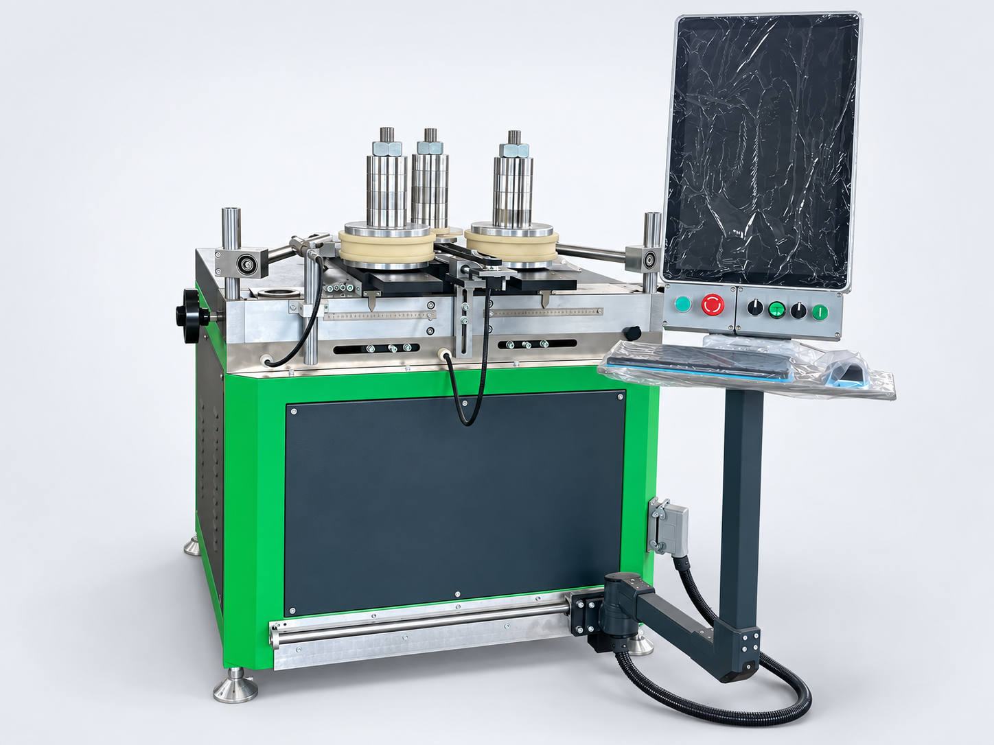
Four-servo CNC
MGW-CNC-15T
Four-servo control for architectural profiles and repeat production.
15 Trated force8 kWcatalog power
Explore this machine →
A larger platform for demanding industrial profile sections.
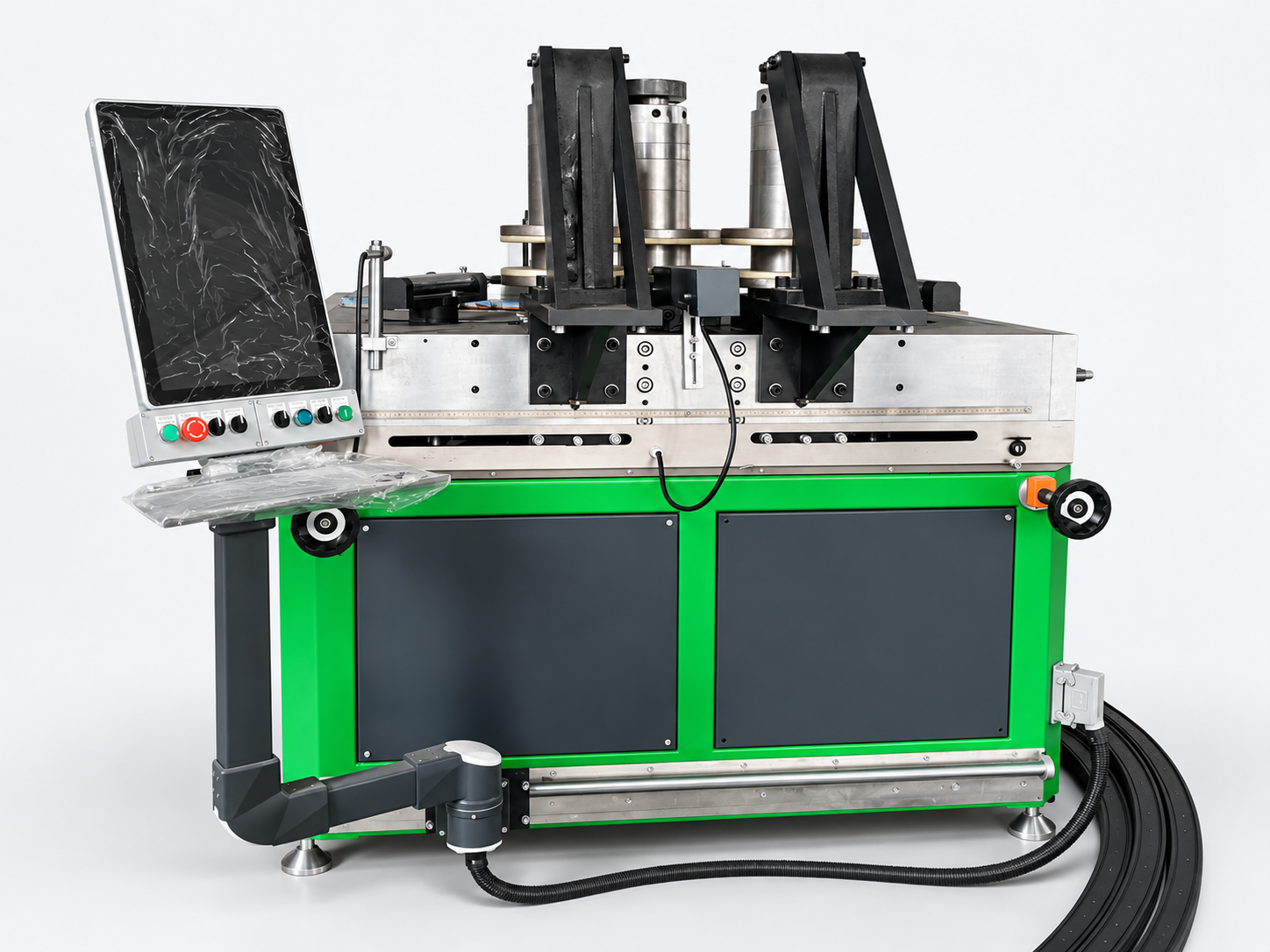
A wider catalog section envelope and heavier platform make the 40T a candidate for larger industrial work. Variable-radius planar shapes require a confirmed program and tooling setup.
Include profile length, handling requirements and workshop space. Long or heavy parts may need additional support during feeding and unloading.
| Model | MGW-CNC-40T |
|---|---|
| Drive arrangement | 3 servo + 2 asynchronous motors + hydraulic |
| Rated Y-axis force | 40 T |
| Total installed power | 21 kW |
| Catalog axis positioning / repeat positioning accuracy | < 0.02 mm |
| Reference minimum bend radius | 150 mm |
| Axis spacing | 450–1200 mm |
| Reference profile width limit | 300 mm |
| Reference profile height limit | 300 mm |
| Catalog section-envelope area limit | 24,000 mm² |
| Machine dimensions | 1900 × 2000 × 1750 mm |
| Machine weight | 3,300 kg |
Source: supplied 2025 catalog, printed pages 14 / 15. Figures describe the catalog configuration. Width, height and area limits are separate checks, not a promise that every section within the envelope can be bent. Standard aluminum data uses 6063-T5 with 1.5 mm wall thickness; the heavy-duty 70T requires a project-specific review. Minimum radius depends on section and tooling. Axis positioning accuracy is not finished-part accuracy. Final specifications are confirmed in the quotation.
The quoted drive arrangement controls the machine axes used to feed and form the profile. The final axis functions and control configuration are confirmed for the ordered machine.
CNC control supports repeatable machine movements for suitable batch jobs. Finished-part consistency still depends on material, tooling, setup and the agreed inspection method.
Rollers and supports are reviewed against the complete cross-section, bending direction and protected surfaces before the configuration is confirmed.
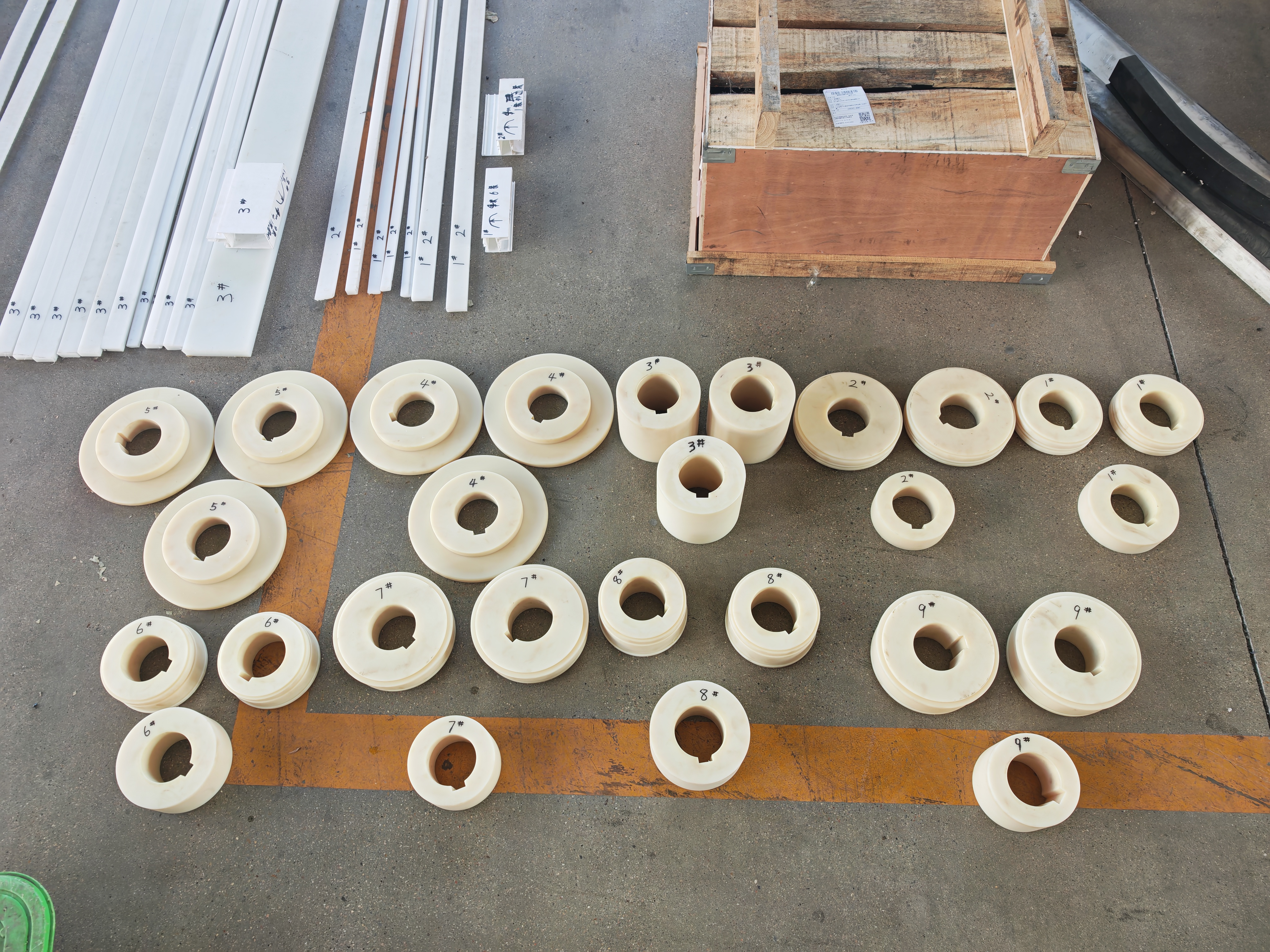
Profile chambers, visible surfaces and bending direction influence roller geometry and support. We review these details before confirming tooling.
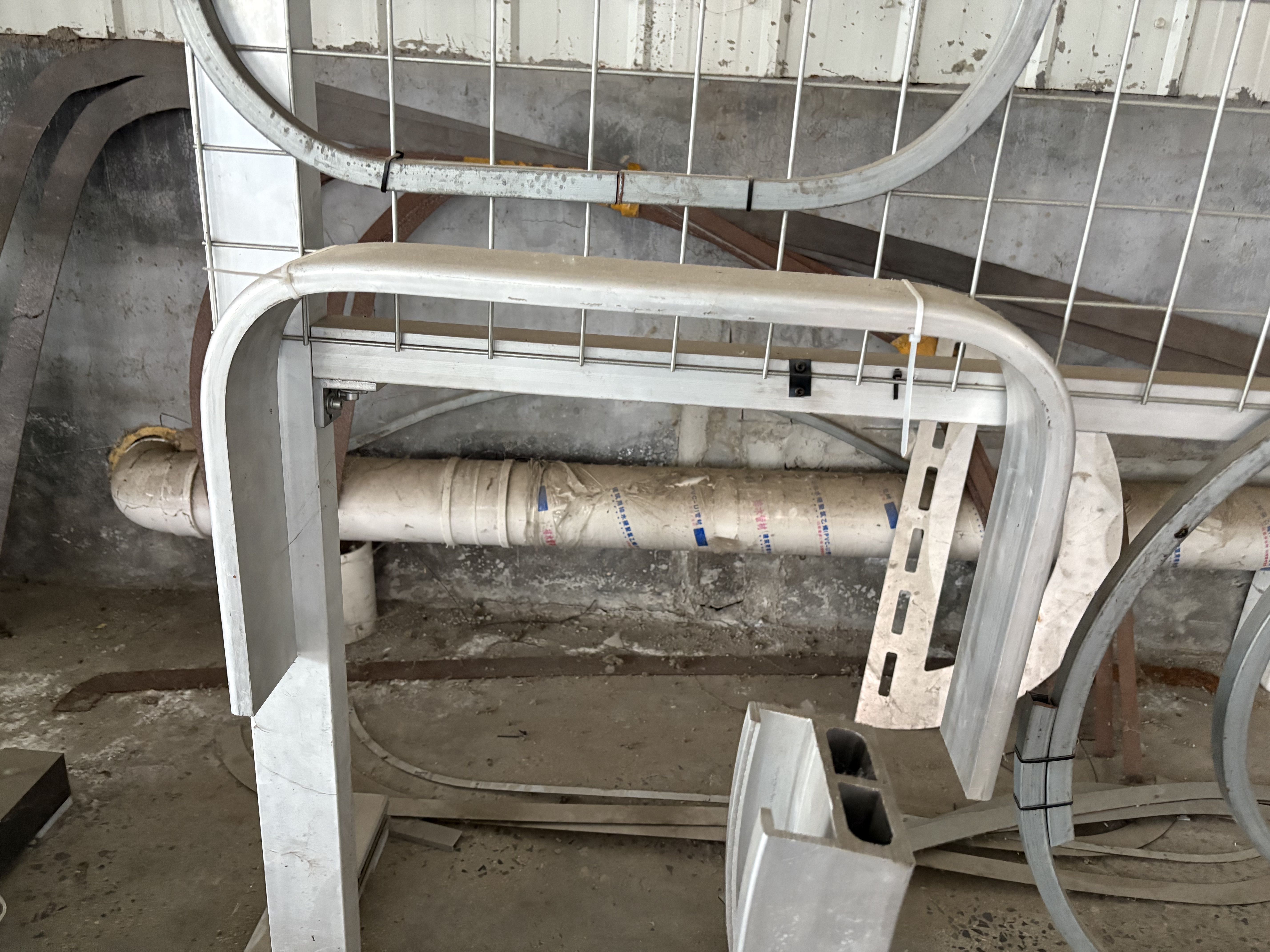
These supplied sample and inspection photos illustrate the review process. They are not a capacity or accuracy claim for this individual model. Send your actual material for a model-specific trial.

Confirm the machine configuration, roller tooling, profile supports, controls and electrical supply included in the quotation.
Confirm production schedule, trade terms, packing, shipping scope, final dimensions and unloading requirements for your site.
Confirm remote or on-site commissioning, operator training, warranty coverage, service contacts and the recommended spare-parts list.
Include profile length, handling requirements and workshop space. Long or heavy parts may need additional support during feeding and unloading. Send your drawing for engineering confirmation.
No. Axis positioning accuracy describes machine motion. Final geometry also depends on material variation, springback, tooling, setup and measurement. Agree on a test and acceptance criteria for your part.
We provide free test bending. Contact us first to agree on sample quantity, length, the test plan and shipping arrangements. Production tooling and the final configuration are confirmed in the quotation.
The machine warranty is 18 months, with coverage and terms stated in the sales agreement. Remote video guidance is available for installation and training. On-site commissioning can also be arranged; scope, travel and costs are agreed in advance.
Tell us your site voltage, frequency and phase. Export electrical configurations are reviewed before the order is confirmed.
The quotation follows drawing review and covers the agreed configuration, tooling, packing and delivery terms. Pricing and delivery time depend on the job and current production schedule.
Four-servo control for architectural profiles and repeat production.
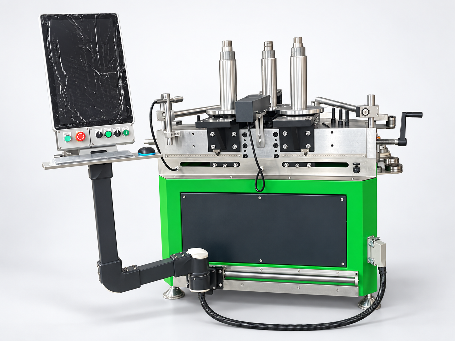
More force for larger architectural and industrial sections.
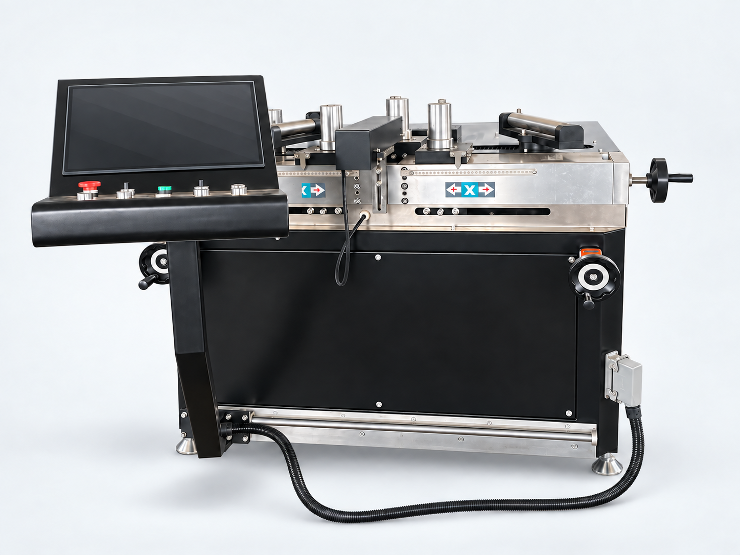
Move beyond a single plane with controlled 3D profile bending.
Send a drawing or clear section photos, material, wall thickness and target radius. Our engineers will review the job and recommend a machine and tooling arrangement.
 Chinese