
2D or 3D profile bending: which do you need?
Identify whether your part stays in one plane or requires a spatial path.
SMT editorial guide · 3 min read
Check the part path
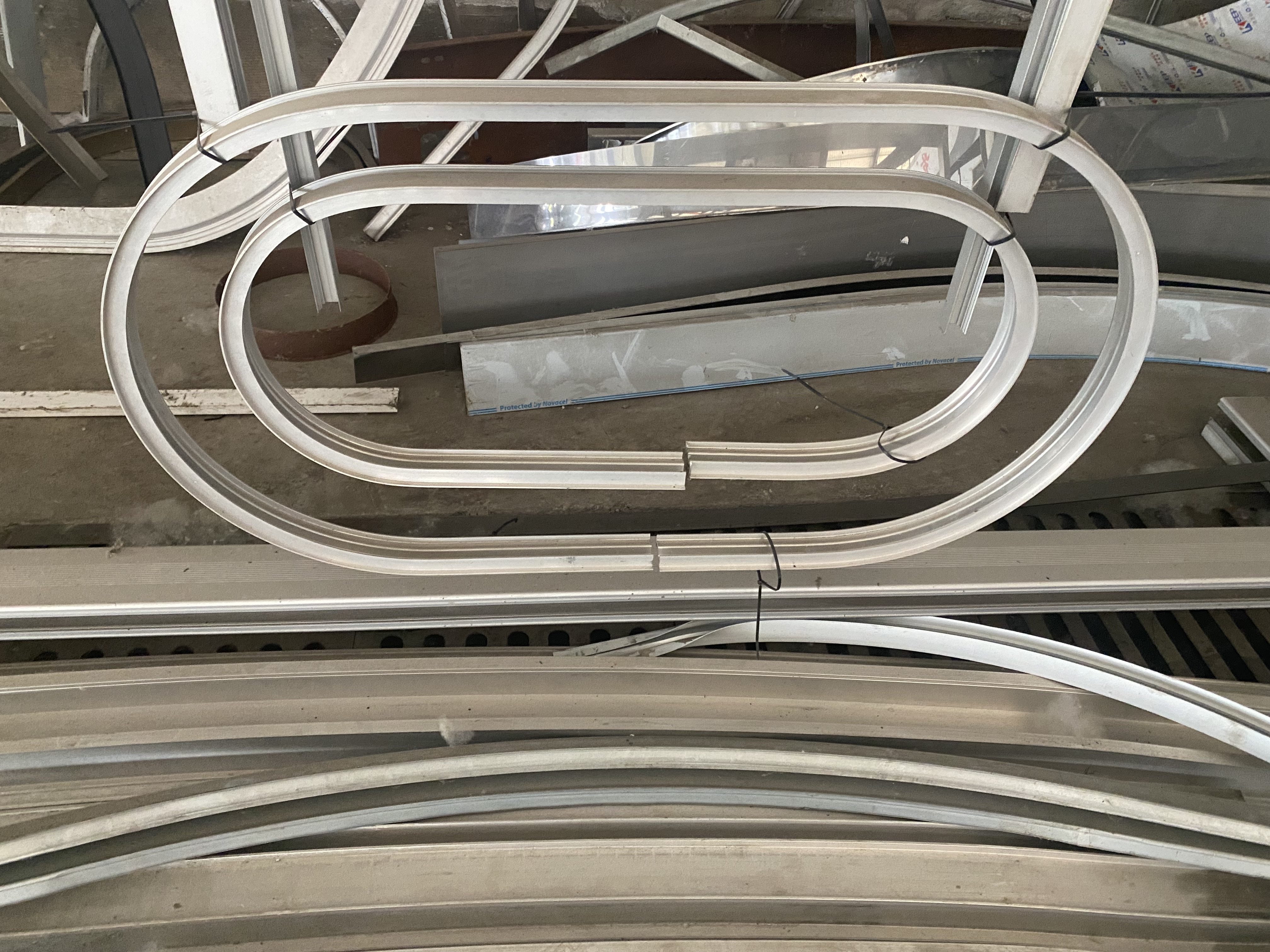
A planar arc can be described within one plane. A spatial part changes direction outside that plane, and its section orientation may change too. Start from the finished part drawing. Several separately joined planar parts should not automatically be treated as one 3D bending job.
Send more than one radius
For a 3D requirement, provide the path and section orientation at relevant locations. Mark end directions, joining faces and measurement datums. Without a 3D model, provide dimensioned views and ask which additional information is needed. This reduces ambiguity when comparing machine configurations.
Include assembly constraints
A bent rail or frame may need to align with brackets, panels or adjacent sections. These interfaces determine which dimensions matter most. Identify visible surfaces and whether twisting is intended or is a defect. Tooling and support depend on these details as well as material.
Review a suitable configuration
The supplied range includes planar machines and the six-servo 3DGW-CNC-15T. Selection depends on the complete part. A 3D-capable machine is not a universal solution for every spatial curve: radius, section support, movement range and access still need engineering review.
Agree how to measure the result
Choose reference points, fixtures and unloaded measurement conditions before testing. One radius reading cannot describe an entire spatial shape. Send SMT the drawing to review the machine and test approach.
Which machine fits your profile?
Send a drawing or clear section photos, material, wall thickness and target radius. Our engineers will review the job and recommend a machine and tooling arrangement.
 Chinese